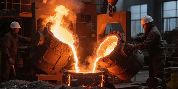
DC Electric Arc Furnace
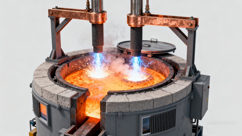
DC (direct current) electric arc furnace (EAF) is a furnace for primary steelmaking which represents a different concept in the designs of arc furnaces. DC-EAF has only a single electrode which acts as a cathode and the current flows down from this graphite electrode to an anode which is mounted in the bottom of the furnace. Single graphite electrode exploits the highly efficient heat transfer of the arc generated between the graphite top electrode and the anode provided by the charge of the furnace. A typical view of a DC-EAF is shown in Fig 1.

Fig 1 Typical view of DC-EAF
DC-EAF arc furnace typically comprises a refractory lined cylindrical steel shell, with a central graphite electrode vertically positioned through an opening in the centre of the roof. The anode connection in the hearth of the furnace is in direct contact with the layer of liquid steel which is covered by a layer of the liquid slag. The energy is supplied by means of an open plasma arc (Fig 2) which is generated between the bottom tip of the cathode and the upper surface of the molten slag. At least a central portion of the slag surface is open. Because the furnace is electrically powered, very high temperatures (higher than 1500 deg C) can be attained.
DC-EAF is an alternative to the AC (alternating current) based EAF. The output of the UHP (ultra high power) transformer is converted to DC using a power rectifier usually bridge connected thyristors. DC-EAF equipped with controllable high power rectifier systems ensures a stable arc under all conditions, at the maximum possible power ratings. The arc in a DC-EAF is a sustained high-velocity high-temperature jet, driven by electromagnetic acceleration (the Maecker effect) in the constricted region near the arc’s root on the electrode surface. The arc is generated by the interaction between the fluid flow, the thermal field, and the electromagnetic fields. The self-constricting electromagnetic forces keep this supersonic super-heated plasma jet (Fig 2) reasonably coherent. A DC reactor is used to stabilize the arc further. Furthermore, the surface of the liquid bath (or at least a portion of the surface in the arc attachment zone) is open, i.e. essentially uncovered by unreacted feed material. Schematic diagram of a DC-EAF is shown in Fig 2.
DC-EAF operations
The progress in high power semiconductor switching technology brought into existence low cost efficient DC power supplies. Due to these advances, the high power DC furnace operation became feasible. The DC-EAF is characterized by rectification of three phase furnace transformer voltages by thyristors controlled rectifiers. These devices are capable of continuously modulating and controlling the magnitude of the DC arc current in order to achieve steady operation. DC furnaces use only one graphite electrode with the return electrode integrated into the furnace bottom. There are several types of bottom electrodes conductive hearth bottom, conductive pin bottom, single, or multiple billet, and conductive fins in a monolithic magnesite hearth.
All of these bottom return electrode designs have been proven. The ones which appear to be used most often are the conductive pin bottom where a number of pins are attached to a plate and form the return path and the bottom billet design. The bottom electrode is air cooled in the case of the pin type and water-cooled in the case of the billet design. The area between pins is filled with ramming mass and the tip of the pins is at the same level as the inner furnace lining. As the refractory wears, the pins also melt back.
DC-EAFs operate with a hot heel in order to ensure an electrical path to the return electrode. During startup from cold conditions, a mixture of scrap and slag is used to provide an initial electrical path. Once this is melted in, the furnace can be charged with scrap.
Some of the early benefits achieved with DC operation included reduced electrode consumption (20 % lower than high voltage AC, 50 % lower than conventional AC), reduced voltage flicker (50 % to 60 % of conventional AC operation) and reduced power consumption (5 % to 10 % lower than for AC). The above results have been mainly achieved on smaller furnaces which were retrofitted from AC to DC operation. However, some larger DC furnace installations did not immediately achieve the claimed benefits. Especially, two areas of concern emerged namely (i) electrode consumption, and (ii) refractory consumption.
Several DC furnace operations found that the decrease in electrode consumption expected under DC operation did not occur. Much analysis by the electrode producers indicated that physical conditions within the electrodes are different for AC and DC operations. As a result, for large DC electrodes carrying very large current, an increased amount of cracking and spalling has been observed as compared to AC operations. Hence, it has become necessary to develop electrodes with physical properties better suited to DC operation.
The economical maximum size for DC furnaces tends to be a function of limitations due to electrode size and current carrying capacity. At the present time the maximum economical size for a single graphite electrode DC furnace appears to be around 165 tons. Larger furnace sizes can be accommodated by using more than one graphite electrode.
Several of the early DC operations have experienced problems with refractory wear and bottom electrode life. These problems are directly related to arc flare within the furnace. The anode design has the greatest influence on the arc flare. In all DC furnaces, the electric arc is deflected in the direction opposite to the power supply due to asymmetries in magnetic fields which are generated by the DC circuit. Thus the arc tends to concentrate on one area within the furnace creating a hot spot and resulting in excessive refractory wear. Several solutions have been developed to control or eliminate arc flare. All the bottom electrode designs are presently configured to force the arc to the centre of the furnace.
In the case of bottom conductive refractory and the pin type bottom, it is necessary to provide split feed lines to the bottom anode or a bottom coil which helps to modify the net magnetic field generated. In the billet bottom design, the amount of current to each billet is controlled along with the direction of anode supply in order to control the arc. The bottom fin design utilizes the fact that electrical feed occurs at several points in order control arc deflection. Quadrants located further from the rectifier are supplied with higher current than those located closer to the rectifier.
Some feel that the possibility for increased automation of EAF activities is greater for the DC furnace. This is because with only one electrode, there is increased space both on top and within the furnace. DC furnace is expected to cost from 10 % to 35% more than a comparable AC furnace. However, calculations on payback indicate that this additional cost can be recovered in one to two years due to lower operating costs.
A study has been conducted which has compared AC and DC furnace operations and it has been found that the electrical losses amount to around 4 % in AC operations and 5.5 % in DC operations with the difference in absolute terms is relatively insignificant. The difference in total energy consumption between AC and DC furnaces is likely to be less than 9 kWh/ton in favour of the DC furnace. However many other variables influence the power consumption and it is difficult to develop accurate figures.
DC furnaces experience roughly 25 % less electrode consumption than AC furnaces, this correlating to typically 0.4 kg/ton. This difference appears to be greater for smaller AC furnaces. Flicker is around 60 % lower for DC operations, however, advances in AC power system configurations (additional reactance) has reduced this difference to 40 %.
Some typical results which have been presented for large DC EAF operations are electrode consumption of 1 kg /ton to 2 kg/ton liquid steel, power consumption in the range of 350 kWh/ton of liquid steel to 500 kWh/ton of liquid steel, tap-to tap time ranging from 45 minutes to 120 minutes, and bottom life of 1,500 heats to 4,000 heats. It is important to remember however, that power consumption is highly dependent on operating practices, tap temperature, use of auxiliary fuels, scrap type etc.
| DC Submerged Arc Furnace For Smelting |
| DC Submerged Arc Furnace For Smelting |
| Developments of DC Submerged Arc Furnace Technology for Ferroalloys in China |
| Electric smelters and submerged arc furnaces |
| DC Arc Furnaces — Past, Present, and Future |
| DC Arc Furnace Technology Applied to Smelting Applications |
| DC Electric Arc Furnaces Steel Scrap Melting Furnace 100kg 5t Eaf |
| DC Submerged Arc Furnace Manufacturer – CHNZBTECH |
| saf submerged arc furnace |
| 20kg-50KG DC Small Submerged Arc Furnace |
| Submerged Arc Furnace at Best Price in India |
| Submerged Arc Furnaces |
| Electric Arc Furnace VS Submerged Arc Furnace |
| Engineering-Scale DC Arc Furnace Testing Summary |
| (PDF) Some myths about DC arc furnaces |
| Submerged Arc Furnace – an overview |
| Submerged Arc Furnace Market Size |
| Submerged Arc Furnace Market Size – By Product Type, By Application, Growth Forecast, 2025 – 2034 |
| How Does a DC Arc Furnace Work? |
| Dc Submerged arc furnace |
| DC Arc Single Electrode Smelting Furnace Mr B Kjellberg |
| Three-dimensional computational fluid dynamics analysis of an electric submerged arc furnace |
| Dc Submerged Arc Furnace at Best Price in Kolkata |
| How DC Submerged Arc Furnaces Revolutionize Ferrochrome Production |
| Comparative Study of AC and DC Solvers Based on Current and Power Distributions in a Submerged Arc Furnace |
| DC Submerged-Arc Furnace With Twin Electrodes For The Fused Magnesia Production |
| Submerged Arc Furnace Market, Share & Forecast to 2035 |
| Submerged ARC Furnaces Market Size and Share Forecast Outlook 2025 to 2035 |
| Submerged Electric Arc Furnace |
| DC Submerged Arc Furnace For Smelting |
| Submerged Arc Furnaces Market Analysis 2025 |
| DC Submerged Arc Furnace |
| DC Submerged Arc Furnace for Enhanced Energy Efficiency and Output |
| New trends in submerged arc furnace technology |
| SAF Submerged Electric ARC Furnace Manufacturer/Supplier |
| Computational analysis of a twin-electrode DC submerged arc furnace for MgO crystal production |
| Submerged electric arc furnace |
| DC Submerged Electric Arc Furnace Started Production |
| Working Principle of the Safety-Sealed Manganese-Silicon |
| Asia Pacific and Middle East & Africa Submerged Arc Furnace |
| Metallic Silicon DC Submerged Arc Furnace |
| Comparison results as received between AC and DC |
| Heavy Duty DC Submerged Arc Furnace for Efficient Metal Processing |
| Submerged Arc Furnace Equipment Market |
| Development in the design and construction of DC arc |
| Pragmatic analysis of the electric submerged arc furnace |
| Submerged Arc Furnaces Market Size And Forecast |
| DC electric arc furnace’s formation and structure |
| Submerged Arc Furnace |
| Types of DC Electric Arc Furnace |
| Energy-saving DC twin shell arc furnace for melting low-grade scrap |
| The Submerged Arc Furnace (SAF) – RWTH Aachen |
| Products › Ironmaking and steelmaking › Electric Arc … |
| Rectifiers for DC Arc Furnace |
| DC electric arc furnace for waste melting and gasification |